Rank placement constrains the physical communication path. Every parallelism axis in the preceding sections was defined by a process group: a list of ranks that must communicate. The list defines the participants but does not predict communication cost. Two groups of the same size may lie inside one NVLink domain or span an InfiniBand fabric. They may also communicate at different frequencies: once per optimizer step or at every routed layer. Parallelism determines what moves and how often; rank placement determines the available physical paths. Together, they affect latency, usable bandwidth, interference, and end-to-end cost.
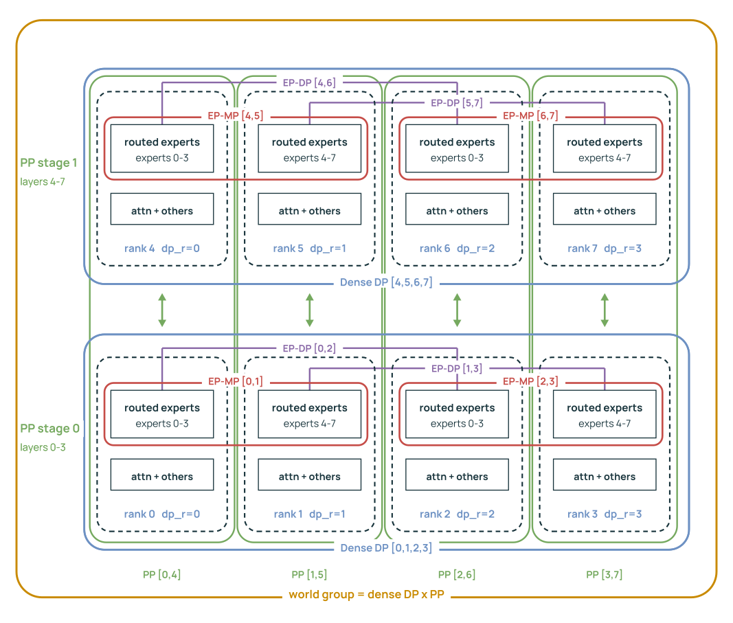
Figure 28 recalls the logical topology from the preceding sections. PP divides layer ranges. Within each stage, EP-MP ranks hold different expert shards, EP-DP ranks hold replicas of the same shard, and dense parameters reduce over the full data-parallel group. PP groups connect matching coordinates across layer stages. The diagram leaves physical placement unspecified: the same logical edge may stay inside a node or cross the network.
Figure 28Interactive · conceptual group membership, not a hardware placement
One rank joins four groups at once
Conceptual redrawing of the report’s illustrative eight-rank example (PP = 2, DP = 4, EP-MP = 2, EP-DP = 2; context parallelism omitted). Group lists follow the mesh order of Section 7.1; “By rank number” lists the same ranks in global order with their MoE mesh coordinates. Quoted lines come from the figure caption, the opening of Section 7, Sections 7.1 and 7.3, Table 11 and Table 3; no placement on hardware is implied.
Original report figure
7.1 Rank Order Turns a Mesh into Placement
The mesh builder arranges rank numbers. Olmo-core constructs its device mesh without consulting a switch table or adapter inventory. It orders the dense mesh as PP, then data parallelism (DP), then context parallelism (CP), so CP varies fastest. MoE layers take a second view of the same per-stage ranks, refolding the combined DP–CP pool into EP-DP and EP-MP with \(DC = D_E M_E\) for CP degree \(C\) (Appendix F). Ranks are laid out in row-major order, so whichever dimension sits innermost occupies contiguous global ranks: CP in the dense view, EP-MP in the MoE view. A PP group varies the outermost dimension and strides by the width of one pipeline stage.
For the eight-rank example in Figure 28, the resulting groups are \[\begin{aligned} \text{EP-MP:}&\quad [0,1], [2,3], [4,5], [6,7],\\ \text{EP-DP:}&\quad [0,2], [1,3], [4,6], [5,7],\\ \text{PP:}&\quad [0,4], [1,5], [2,6], [3,7]. \end{aligned}\] With eight contiguous local ranks per node, EP-MP occupies the innermost, adjacent ranks, so at the production degree of eight an EP-MP group fills exactly one NVL8 domain—eight GPUs on one NVLink fabric (Section 7.4). PP groups and the replica groups, which usually span several nodes, stride across those local blocks. This layout keeps frequent, irregular EP traffic on NVLink. An EP-MP group wider than eight has to leave the node.
This mapping follows from mesh dimension order and launcher rank order, with no topology optimizer. Reordering the hostfile, changing the number of local ranks, or choosing a stage width that does not divide the node can change the physical mapping even when the parallelism degrees stay the same. Rank order therefore belongs in the recorded performance configuration.
7.2 GPUDirect RDMA Moves Payload; IBGDA Submits Work
Payload movement and work submission have separate costs. Inside one NVL8 node, a GPU reaches peer GPU memory through the NVLink/NVSwitch fabric. Across nodes the path is longer: \[\text{GPU memory} \rightarrow \text{PCIe} \rightarrow \text{local HCA} \rightarrow \text{InfiniBand} \rightarrow \text{remote HCA} \rightarrow \text{PCIe} \rightarrow \text{remote GPU memory}.\] The host channel adapter (HCA) is InfiniBand’s name for the network adapter—the NIC of Section 5.8—and it connects to the GPU through PCIe, which is why PCIe appears at both ends of every cross-node transfer. The nominal fabric rate is only one limit: GPU–HCA locality, shared PCIe bridges, rail selection (which of the node’s per-GPU adapters carries the transfer, Section 7.4), message size, and concurrent traffic can each become the limiting segment. The chain above is conceptual, since NCCL or NVSHMEM may select another local adapter or relay path, and only runtime diagnostics establish the route actually used.
GPUDirect RDMA lets an HCA read and write GPU memory directly, removing a host-memory bounce buffer from the payload path (NVIDIA 2026e); a host thread or proxy may still be the one preparing the work. InfiniBand GPUDirect Async (IBGDA), as used by NVSHMEM, can move that preparation onto the GPU for one-sided operations (NVIDIA 2026s; Markthub et al. 2022). Symmetric memory (Section 5.5) already makes remote expert rows addressable; the GPU-driven IBGDA path lets the rowwise EP kernel submit the inter-node transfer itself, with no CPU proxy preparing the work.
The two mechanisms are independent: a direct payload path removes staging copies, and GPU-side submission removes a host dependency from the critical path. Both still require completion ordering and memory registration, and rowwise EP transfers also depend on the lifetime rules of the remotely visible symmetric buffers. Section 8.4 follows the host-synchronization consequence in detail.
7.3 Communication Clock Determines Placement Priority
Table 11 combines what moves with when it moves. A single DDP collective can carry more bytes than a single EP dispatch, but it runs once per optimizer step and several accumulation microbatches share its cost. EP and PP communication recurs inside every microbatch, and full-reshard FSDP repeats parameter materialization at every wrapped execution boundary. Placement must account for this frequency and critical-path sensitivity as well as byte count.
| Axis | Traffic and clock | Placement consequence |
|---|---|---|
| DDP / optimizer | Parameter-sized gradient and updated-parameter buckets, once per optimizer step | Bandwidth and rail balance matter; accumulation microbatches amortize this boundary cost. |
| Full-reshard FSDP | Parameter shards materialized into full wrapped weights, around each wrapped microbatch execution | Repetition makes remote placement costly even when each collective is regular. |
| EP-MP | Routed token rows and returned expert outputs, at every routed layer in forward and backward for every microbatch | Fast locality, low latency, route balance, and small-message behavior all matter. |
| PP | Hidden activations and their gradients, at every remote stage boundary for every microbatch | Physical adjacency and independent-work windows determine the exposed P2P cost. |
The axes also use different communication libraries. Dense DDP and EP-DP reduction use NCCL collectives; PP uses NCCL point-to-point communication; block all-to-all EP uses an NCCL all-to-all collective; and the rowwise EP-MP path uses NVSHMEM symmetric memory, because it benefits from indexed one-sided movement among the ranks of an EP-MP group.
7.4 The Tested System Has Eight GPUs per NVLink Domain
The audited cluster used for the main training experiments has eight NVIDIA B300 SXM6 GPUs per node in a single NVLink domain, with every GPU pair reported as NV18 (eighteen NVLink links per GPU). Each node reaches the fabric over eight active 800-Gb/s-class XDR InfiniBand rails, one aligned to each GPU across a shared PCIe bridge (PXB) (NVIDIA 2026b, 2026t). This is an NVL8 system: any parallel group wider than eight leaves the NVLink domain and crosses the fabric.
These specifications describe hardware capabilities, not achieved bandwidth. “One local rail per GPU” describes a favorable GPU–HCA pairing in the physical topology; which rail a given NCCL or NVSHMEM transfer actually used is a separate question. Enabling an IBGDA environment option is likewise a request rather than evidence that the effective handler mode was fully GPU-side. The rail and IBGDA statements in this report therefore describe the configured paths, taken from the audited inventory and requested configuration rather than per-transfer counters.
The distinction matters most when comparing training systems. An NVL72 domain keeps much larger model-parallel groups on NVLink, so results measured there and our NVL8 measurements are not an apples-to-apples topology comparison. The comparison can also run the other way: the unusually well-provisioned XDR fabric on these nodes can flatter an inter-node method that would fare worse on a cluster with fewer or slower rails. Comparing systems therefore requires the end-to-end path available to each rank group, not just the GPU and fabric names.
7.5 Topology Changes the Operating Point
Increasing EP-MP degree from eight to sixteen halves each rank’s expert shard, but also moves EP from an intra-node NVLink exchange to an inter-node operation, and it can change which backend is worth using: many small row transfers can become limited by the HCA’s message rate, favoring the block-oriented DeepEP v2 backend (Section 5.8). Where the crossover falls is an empirical property of model shape and fabric rather than a universal degree threshold.
Adding accumulation microbatches spreads DDP gradient and optimizer-boundary traffic across more useful token work, while EP dispatch/combine and PP activation traffic recur for every microbatch regardless. One batch-size change can therefore relieve one communication axis and, at the same time, make another communicate more often.
Separate communicators or CUDA streams still use the same hardware. Concurrent communication and GEMM can still contend for SM scheduling, cache, memory bandwidth, PCIe, HCAs, and fabric links. Section 5.9 shows this directly in one two-node EP-MP\({}=16\) diagnostic, where concurrent rowwise communication slowed the grouped expert work by roughly 23–27% on the tested shape. The magnitude is specific to that shape. As Section 5.9 shows, the benefit of hidden communication must be evaluated together with the slowdown of concurrent kernels.
Parallelism defines which values communicate and how often; mesh dimension order and launcher rank order turn those logical groups into physical paths. Our placement gives frequent, latency-sensitive traffic priority within the NVLink domain, subject to the launcher producing the intended mapping. Changing degree, batching, backend, or overlap policy can change the limiting resource, so their combined effect is specific to each model and hardware configuration.